·
Pre-Bunker Checklist
Bunkerline pressure testing :Bunker lines are required to be tested to 1.5 times their allowable operating pressure by placing them under a constant hydro static load for a prescribed period of time (usually 5-10 minutes is sufficient). This is best achieved by using the FO transfer pump (s) to fill bunker lines up to the manifolds (with fuel oil), purge the lines via manifold valves, then build pressure in the lines until 1.5 times the normal operating pressure is reached (operating parameters should be available in the bunker plan, or the vessel may be guided by pipeline material pressure ratings).If the FO transfer pump is a positive-displacement type, it may be stopped when the required test pressure is reached as it should not permit back flow. If a centrifugal type of pump is employed, constant running will be required to ensure the necessary pressure is maintained during the test. In addition to log entries in Deck Logbook and Oil Record Book (ORB), the deck bunker lines are also required to be stenciled with the date of last pressure test together with the pressure maintained (in kg/cm2, psi or bar)..
· During Bunkering Procedures - Checklist
Bunkering Precautions :
Precautions during Bunkering
Precautions to be observed when bunkering are:
All scuppers to be plugged so that in the event of a small spillage 1. onto the deck it
is contaminated and can be dealt with.
2. Drip trays must be placed under the ship-shore connection.
3. Good communication between ship and shore must be established and checked to
regulate flow as desired.
4. Personnel operating the system must be fully conversant with the layout of pipes,
tanks, valves etc.
5. Moorings and hose length should at all times be such that there is no possibility of
stretching or crushing the hose.
6. Ensure blank at opposite end of cross-over pipe is securely in place.
7. Air pipes should be clear, soundings checked and depth indicators tested.
When transferring oil within the ship it should ideally be done during the hours of
daylight, the overboard discharge connections should be closed and secured. Overflow
alarm should be tested and soundings taken at frequent intervals.
All transfers must be recorded in the Oil Record Book.
Using empty oil fuel tanks as ballast tanks should be avoided as far as possible, since
the ballast will eventually have to be discharged.
·
Quantity Calculation & Temperature-Density Correction:
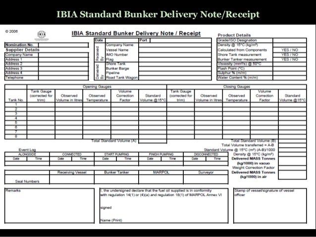

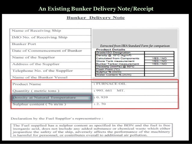
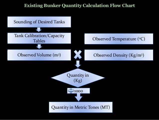
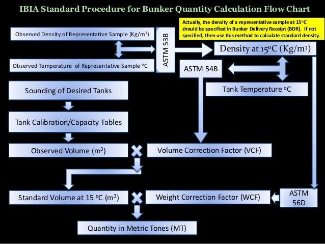
Found this on records, so thought to share...
The bunker calculation is simple and needs the following:
- Tank Sounding data and Tank Capacity Table. The Corrected Sounding means below is the sounding after correcting with vessel’s trim and list.
- Temperature of Oil on Tanks,
- Oil Density @15C,
- Table ASTM 54B (VCF) and Table ASTM 56 (WCF).
Now we could go with sample of 1 tank to test the calculation.
** Question :
FO Tank No. 1 Center, Corrected Sounding = 3.27 Meter, Temperature = 34 degrees celcius, Density @ 15 C = 0.9870.
Tank Volume at Sounding 3.20 M = 157.20 Cubic Meter, at Sounding 3.30 M = 163.60 Cubic Meter.
** Answer :
- The Quantity in Metric Ton = Oil Vol x VCF x WCF,
- Observe Volume = {(3.27 – 3.20) / (3.30 – 3.20) x (163.60 – 157.20)} + 157.20 = (0.07/0.10) x (6.40) + 157.20 = 4.48 + 157.20 = 161.68 Cu.M.
- T 54B (VCF) > Density @ 15C 0.9903 at 34 C = 0.9870
ASTM Table 54B
- T 56 (WCF) : Density @15C 0.9903 at 34 C = 0.9892 (Quick formula with reducing factor for WCF is Density @ 15C – 0.0011 = 0.9903 – 0.0011 = 0.9892). We don’t need to see the table anymore.


Keep your kitchen clean and organized with bar mop towels at wi-supply.com. Our absorbent towels are perfect for mopping up spills and cleaning up messes.
ReplyDelete