Oily Water Separator: Construction and Working
Construction and Working of OWS

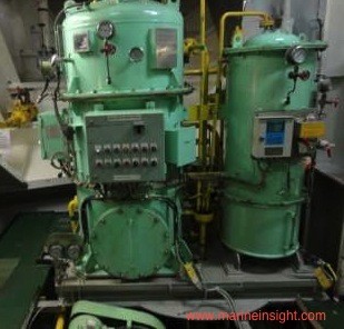
OWS consists of mainly three segments:
Separator unit
- This unit consists of catch plates which are inside a coarse separating compartment and an oil collecting chamber.
- Here the oil having a density which is lower than that of the water, which makes the former rise into the oil collecting compartment and the rest of the non-flowing oil mixture settle down into fine settling compartment after passing between the catch plates.
- After a period of time more oil will separate and collect in the oil collecting chamber. The oil content of water which passes through this unit is around 100 parts per million of oil.
- A control valve (pneumatic or electronic) releases the separated oil in to the designated OWS sludge tank.
- Heater may be incorporated in this unit for smooth flow and separation of oil and water.
- First stage helps in removing some physical impurities to achieve fine filtration in the later stage.
The Filter unit
- This is a separate unit whose input comes from the discharge of the first unit.
- This unit consists of three stages – filter stage, coalescer stage and collecting chamber.
- The impurities and particles are separated by the filter and are settled at the bottom for removal.
- In second stage, coalescer induces coalescence process in which oil droplets are joined to increase the size by breaking down the surface tension between oil droplets in the mixture.
- These large oil molecules rise above the mixture in the collecting chamber and are removed when required.
- The output from this unit should be less than 15 ppm to fulfil legal discharge criteria.
- If the oil content in water is more than 15 ppm then maintenance work such as filter cleaning or renewal of filters is to be done as required.
Oil Content Monitor and Control Unit
- This unit functions together in two parts – monitoring and controlling.
- The ppm of oil is continuously monitored by Oil Content Monitor (OCM); if the ppm is high it will give alarm and feed data to the control unit.
- The control unit continuously monitors the output signal of OCM and if alarm arises, it will not allow the oily water to go overboard by means of operating 3 way solenoid valve.
- There are normally 3 solenoid valves commanded by control unit. These are located in the first unit oil collecting chamber, second unit oil collecting chamber and one in discharge side of the oily water separator which is a 3 way valve.
- The 3 way valve inlet is from the OWS discharge, where one outlet is to overboard and second outlet is to OWS sludge tank.When OCM gives alarm, 3 way valve discharges oily mixture in the sludge tank.
.jpg/513px-Piping_Pic-page0001_(2).jpg)
How to Operate an Oily Water Separator (OWS) on Ship?
Operating an Oily Water Separator
An oily water separatorcan only be operated when the ship is sailing and en route. According to MARPOL, the oil content of the effluent must be less than 15 ppm and the ship has in operation an oil discharge monitoring and control system and oily-water separating/filtering equipment.
 In case of failure to follow any of the above mentioned rules, the ship will be fined and stopped, and the chief or 2nd engineer can even be imprisoned.
Because of such high risks, operating an oily water separator should be done with utmost precision to minimize the risks of marine pollution. Though a “How to Operate?” guide is always posted near the oily water separator, there are few points to be kept in mind and followed to prevent any mistake.
Operating Procedure
The following points are to be followed while operating OWS.
1) OWS overboard manual discharge valve is to be kept locked and keys are to be kept with the chief engineer. Open the lock and overboard valve. Open all the other valves of the system.
2) Open the desired bilge tank valve from which the oily water mixture is to be discharged from OWS.
3) Open air if the control valves are air operated.
4) Switch on the power supply of the control panel and OCM unit.
5) Fill the separator and filter unit with fresh or sea water to clean up and prime the system till the water comes out from vent of second stage.
6) Start the OWS supply pump which is a laminar flow pump and one that will supply the oily water mixture to OWS.
7) Observe the OCM for ppm value and keep checking sounding of bilge tank from where OWS is taking suction and of the OWS sludge tank.
8 ) A skin valve/sample valve is provided just before overboard valve and after the 3-way valve. Keep a check on the sample for any effluent and clarity.
9) Keep a watch on the ship side at the overboard discharge valve.
10) After the operation, Switch off the power and shut and lock the overboard valve. Keys to be handed over to the chief engineer.
11) Entry to be made by chief engineer in the Oil Record Book (ORB) with signature of operating officer, chief engineer and the master.
Operating an Oily Water Separator
An oily water separatorcan only be operated when the ship is sailing and en route. According to MARPOL, the oil content of the effluent must be less than 15 ppm and the ship has in operation an oil discharge monitoring and control system and oily-water separating/filtering equipment.
In case of failure to follow any of the above mentioned rules, the ship will be fined and stopped, and the chief or 2nd engineer can even be imprisoned.
Because of such high risks, operating an oily water separator should be done with utmost precision to minimize the risks of marine pollution. Though a “How to Operate?” guide is always posted near the oily water separator, there are few points to be kept in mind and followed to prevent any mistake.
Operating Procedure
The following points are to be followed while operating OWS.
1) OWS overboard manual discharge valve is to be kept locked and keys are to be kept with the chief engineer. Open the lock and overboard valve. Open all the other valves of the system.
2) Open the desired bilge tank valve from which the oily water mixture is to be discharged from OWS.
3) Open air if the control valves are air operated.
4) Switch on the power supply of the control panel and OCM unit.
5) Fill the separator and filter unit with fresh or sea water to clean up and prime the system till the water comes out from vent of second stage.
6) Start the OWS supply pump which is a laminar flow pump and one that will supply the oily water mixture to OWS.
7) Observe the OCM for ppm value and keep checking sounding of bilge tank from where OWS is taking suction and of the OWS sludge tank.
8 ) A skin valve/sample valve is provided just before overboard valve and after the 3-way valve. Keep a check on the sample for any effluent and clarity.
9) Keep a watch on the ship side at the overboard discharge valve.
10) After the operation, Switch off the power and shut and lock the overboard valve. Keys to be handed over to the chief engineer.
11) Entry to be made by chief engineer in the Oil Record Book (ORB) with signature of operating officer, chief engineer and the master.
Oily Water Separator (OWS) Maintenance Tips Every Ship Engineer Must Know:
Every engineer on ship knows the importance of oily water separator (OWS) and must have heard stories of legal actions taken against seafarers who tried to fiddle or bypass the automation system of the OWS.
 The most common cause of people tempering with oily water separator is deterioration of performance of the system.
Apart from the filter getting clogged due to continuous usage, there can be many other reasons for the lack of performance.
A few critical points, which are often ignored and less commonly known to engineers operating oily water separator on daily basis, are discussed in this article to ensure efficient performance of oily water separator (coalesce filter type) used onboard ships:
1. Oil In Bilge: The separator is suitable for separating small quantity of oil in bilge and not the other way round. If there is a mixture consisting of small quantity of water in oil, better not to pass it though the OWS and directly transfer it to waste oil tank for sludge disposal to shore or for incineration.
2. Keep Viscosity in Limit: Highly viscous oil if supplied for oily water separation will clog the filter. It is important to keep the viscosity of the oil within 1000 mm2/s
3. Discharge Outside Separator: Never discharge or drain water oil mixture from the separator abruptly out of OWS as it will lead to the separated oil adhere to coalescers, making it inoperative. Ensure to discharge the collected separated oil outside the separator and clean the internals of the OWS by supplying water.
4. Install Dust Filter: While using OWS for discharging bilge mixture containing dust and sand (a coarse grained entity), it will be difficult for the coalescer filter to pass dust and sand due to their sizes. This will reduce the operating hours of the filter and in-turn the efficiency of the OWS. The ideal service life of the filter normally ranges from 1-2 year depending upon the manufacturing process, considering daily operation of one hour. It is advisable to install a dust filter in the inlet line of the OWS to avoid this trouble.
5. Exchanging Probe for Fault Finding: for In most of the 15ppm OWS models, the oil level detecting probe and transmitting convertor in the 1st and 2nd stage chamber are identical. In the event of trouble, exchange these with each other, between the chambers, as this will help in finding out the source of trouble quickly.
6. Keep Check On Heating Device: If a heating device is provided, ensure it is ON when OWS is in operation and switched OFF before OWS is stopped. In case when the OWS is run for a long time, keep a track on the heater for overheating of coils. If the separator is overheated to high extent, there may be some production of inflammable gases inside.
7. Protect Internal Coating: The OWS internals are applied with tar epoxy coating, which is inflammable. Avoid bringing fire near to it or perform welding over the surface or body as the heat generated will damage the coating, making OWS susceptible to corrosion
8. Check Water Level: Ensure that the separator is initially filled with sea water before bilge mixture is supplied to it. This is to increase the life of filters and also to maintain the operational efficiency of the separator
9. Prevent Leakage: Ensure the means provided to avoid leaking or flowing out of water due to siphon effect. Failure to do so will allow oil to flow in the secondary chamber highly affecting the treatment capability of the machine and clogging the 2nd stage filters
10. Check Effluent: Frequent checks on effluent to be done to assess the performance of the separator. If the effluent is found contaminated, immediately stop the separator and take preventive actions
The operator of OWS should be thorough about the system, design, piping arrangement and of course the operating procedure of oily water separator. Out of all the machinery systems, OWS is kept at high priority due to stringent rules and regulations attached to it for ensuring environmental compliance. Hence it is important for the ship staff to maintain this machine in best of its shape.
The most common cause of people tempering with oily water separator is deterioration of performance of the system.
Apart from the filter getting clogged due to continuous usage, there can be many other reasons for the lack of performance.
A few critical points, which are often ignored and less commonly known to engineers operating oily water separator on daily basis, are discussed in this article to ensure efficient performance of oily water separator (coalesce filter type) used onboard ships:
1. Oil In Bilge: The separator is suitable for separating small quantity of oil in bilge and not the other way round. If there is a mixture consisting of small quantity of water in oil, better not to pass it though the OWS and directly transfer it to waste oil tank for sludge disposal to shore or for incineration.
2. Keep Viscosity in Limit: Highly viscous oil if supplied for oily water separation will clog the filter. It is important to keep the viscosity of the oil within 1000 mm2/s
3. Discharge Outside Separator: Never discharge or drain water oil mixture from the separator abruptly out of OWS as it will lead to the separated oil adhere to coalescers, making it inoperative. Ensure to discharge the collected separated oil outside the separator and clean the internals of the OWS by supplying water.
4. Install Dust Filter: While using OWS for discharging bilge mixture containing dust and sand (a coarse grained entity), it will be difficult for the coalescer filter to pass dust and sand due to their sizes. This will reduce the operating hours of the filter and in-turn the efficiency of the OWS. The ideal service life of the filter normally ranges from 1-2 year depending upon the manufacturing process, considering daily operation of one hour. It is advisable to install a dust filter in the inlet line of the OWS to avoid this trouble.
5. Exchanging Probe for Fault Finding: for In most of the 15ppm OWS models, the oil level detecting probe and transmitting convertor in the 1st and 2nd stage chamber are identical. In the event of trouble, exchange these with each other, between the chambers, as this will help in finding out the source of trouble quickly.
6. Keep Check On Heating Device: If a heating device is provided, ensure it is ON when OWS is in operation and switched OFF before OWS is stopped. In case when the OWS is run for a long time, keep a track on the heater for overheating of coils. If the separator is overheated to high extent, there may be some production of inflammable gases inside.
7. Protect Internal Coating: The OWS internals are applied with tar epoxy coating, which is inflammable. Avoid bringing fire near to it or perform welding over the surface or body as the heat generated will damage the coating, making OWS susceptible to corrosion
8. Check Water Level: Ensure that the separator is initially filled with sea water before bilge mixture is supplied to it. This is to increase the life of filters and also to maintain the operational efficiency of the separator
9. Prevent Leakage: Ensure the means provided to avoid leaking or flowing out of water due to siphon effect. Failure to do so will allow oil to flow in the secondary chamber highly affecting the treatment capability of the machine and clogging the 2nd stage filters
10. Check Effluent: Frequent checks on effluent to be done to assess the performance of the separator. If the effluent is found contaminated, immediately stop the separator and take preventive actions
The operator of OWS should be thorough about the system, design, piping arrangement and of course the operating procedure of oily water separator. Out of all the machinery systems, OWS is kept at high priority due to stringent rules and regulations attached to it for ensuring environmental compliance. Hence it is important for the ship staff to maintain this machine in best of its shape.
Every engineer on ship knows the importance of oily water separator (OWS) and must have heard stories of legal actions taken against seafarers who tried to fiddle or bypass the automation system of the OWS.
The most common cause of people tempering with oily water separator is deterioration of performance of the system.
Apart from the filter getting clogged due to continuous usage, there can be many other reasons for the lack of performance.
A few critical points, which are often ignored and less commonly known to engineers operating oily water separator on daily basis, are discussed in this article to ensure efficient performance of oily water separator (coalesce filter type) used onboard ships:
1. Oil In Bilge: The separator is suitable for separating small quantity of oil in bilge and not the other way round. If there is a mixture consisting of small quantity of water in oil, better not to pass it though the OWS and directly transfer it to waste oil tank for sludge disposal to shore or for incineration.
2. Keep Viscosity in Limit: Highly viscous oil if supplied for oily water separation will clog the filter. It is important to keep the viscosity of the oil within 1000 mm2/s
3. Discharge Outside Separator: Never discharge or drain water oil mixture from the separator abruptly out of OWS as it will lead to the separated oil adhere to coalescers, making it inoperative. Ensure to discharge the collected separated oil outside the separator and clean the internals of the OWS by supplying water.
4. Install Dust Filter: While using OWS for discharging bilge mixture containing dust and sand (a coarse grained entity), it will be difficult for the coalescer filter to pass dust and sand due to their sizes. This will reduce the operating hours of the filter and in-turn the efficiency of the OWS. The ideal service life of the filter normally ranges from 1-2 year depending upon the manufacturing process, considering daily operation of one hour. It is advisable to install a dust filter in the inlet line of the OWS to avoid this trouble.
5. Exchanging Probe for Fault Finding: for In most of the 15ppm OWS models, the oil level detecting probe and transmitting convertor in the 1st and 2nd stage chamber are identical. In the event of trouble, exchange these with each other, between the chambers, as this will help in finding out the source of trouble quickly.
6. Keep Check On Heating Device: If a heating device is provided, ensure it is ON when OWS is in operation and switched OFF before OWS is stopped. In case when the OWS is run for a long time, keep a track on the heater for overheating of coils. If the separator is overheated to high extent, there may be some production of inflammable gases inside.
7. Protect Internal Coating: The OWS internals are applied with tar epoxy coating, which is inflammable. Avoid bringing fire near to it or perform welding over the surface or body as the heat generated will damage the coating, making OWS susceptible to corrosion
8. Check Water Level: Ensure that the separator is initially filled with sea water before bilge mixture is supplied to it. This is to increase the life of filters and also to maintain the operational efficiency of the separator
9. Prevent Leakage: Ensure the means provided to avoid leaking or flowing out of water due to siphon effect. Failure to do so will allow oil to flow in the secondary chamber highly affecting the treatment capability of the machine and clogging the 2nd stage filters
10. Check Effluent: Frequent checks on effluent to be done to assess the performance of the separator. If the effluent is found contaminated, immediately stop the separator and take preventive actions
The operator of OWS should be thorough about the system, design, piping arrangement and of course the operating procedure of oily water separator. Out of all the machinery systems, OWS is kept at high priority due to stringent rules and regulations attached to it for ensuring environmental compliance. Hence it is important for the ship staff to maintain this machine in best of its shape.
15 PPM Bilge Alarm
 This 15ppm Bilge Alarm meets the requirements of IMO Resolution MEPC. 107(49). Type-Approval Certificate in according with IMO Resolution MEPC. 107(49) therefore this satisfy international convention.
This 15ppm Bilge Alarm Monitor serves to continuously measure the concentration of oil in the bilge and other waste water produced on a ship, and produces an alarm signal when the oil concentration exceeds 15ppm.
The 15ppm Bilge Alarm should not be affected by emulsions and/or the type of oil and the response time must not exceed 5 seconds. The system must record date, time and alarm status, and also the operating status of the 15ppm Bilge Separator. The recording device must also store data for a minimum period of eighteen months and should be able to display or print a protocol for official inspections and should be so constructed that the alarm is always activated whenever clean water is used for cleaning or zeroing purposes.

| Measuring range | 0 - 30 ppm |
| Measuring accuracy | 15 ppm ± 5 ppm [IMO Resolution MEPC 107(49)] |
| Set point | 0 - 15 ppm |
| Response time | time delay : 0 seconds [below 5 sec.] |
| Alarm contacts / rating | normal / alarm contacts |
| Sources of electricity | AC 100 - 220 V |
| Dimensions | [W] 350 x [L] 270 x [H] 80 mm |
| Weight | ± 10 kg |


:D
ReplyDeleteNice!!
ReplyDeleteThank you for sharing the best information if you are searching the best industrial filter manufacturers so you can go with Engineered Filtration.
ReplyDeleteThey responded quickly in our emergency situation. 24/7 water damage restoration services across New York City
ReplyDeleteThey solved a long-standing plumbing issue. Repipe Company
ReplyDeleteGreat overview of filling machine technology. Efficient and accurate filling solutions are very important for industries like lubricants, especially in a Brake fluid making plant where precision and automation help improve productivity and reduce wastage.
ReplyDeleteYou may want to hire any normal plumber who would sort the issue and charge you less; this is where major problems can arise, just because they charge you less doesn’t make them perfect for your situation, fewer charges can lead to less quality service.Lausier Brothers
ReplyDelete