WHAT MEASURES WHAT?
Now that we are aware of the 4 terms (VOLTAGE, CURRENT, POWER, FREQUENCY) which associated with electricity, lets take a look at what all instruments we need to measure them and how they work.
If you want to measure VOLTAGE we use an instrument called VOLTMETER
If you want to measure CURRENT we use an instrument called AMMETER
If you want to measure POWER we use an instrument called WATTMETER
If you want to measure FREQUENCY we use an instrument called FREQUENCY METER
Lets now briefly take a look at how these instruments work:
VOLTMETER

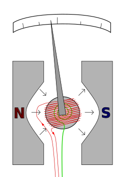
The basic analog voltmeter comprises of a 'pointer' needle which is attached to a movable coil which in turn is mounted on a pivot. The pivot allows the coil to rotate, which lets the pointer swing across the meter face marked with a graduated scale., The coil is situated between two opposing polarity magnets. The coil is also spring loaded so as to keep the needle at zero when no voltage is supplied.When a voltage is applied to the coil, the coil starts to rotate against the spring. As more voltage is applied, more force is generated between the coil and the magnets causing the coil to rotate further. As the coil rotates, the needle moves across the meter face and the voltage can be read from the scale on the meter face.
 |
| Image showing working of a analog voltmeter |
AMMETER

The basic analog ammeter comprises of a 'pointer' needle which is attached to a movable coil which in turn is mounted on a pivot. The pivot allows the coil to rotate, which lets the pointer swing across the meter face marked with a graduated scale., The coil is situated between two opposing polarity magnets. The coil is also spring loaded so as to keep the needle at zero when no current is supplied.When a current is applied to the coil, the coil starts to rotate against the spring. As more current is applied, more force is generated between the coil and the magnets causing the coil to rotate further. As the coil rotates, the needle moves across the meter face and the current can be read from the scale on the meter face.
It looks exactly the same as a voltmeter?
Yes both work on the same principle and their construction is the same however the only difference between the two instruments is the way in which resistors are used, within the instruments, to make one suitable for measuring current and the other suitable for measuring voltage. Always remember that in voltmeters the current which operates the coil is proportional to the voltage appearing across the voltage.
Please note that when we measure voltage, voltmeter, it is connected in parallel to the circuit under test and when measuring current, ammeter, is connected in series to the circuit under test.
WATTMETER

A wattmeter comprises of three coils out of which two are fixed coils which are connected in series with the electrical load, and a moving coil which is called the potential coil in parallel with it. The coil connected in series measure the current flowing through the circuit where as the the parallel coil measures the voltage. Potential coil has a resistor connected in series to it and it carries a needle which moves over a suitably marked scale. The magnetic field in all the three coils influence the needle movement. A spring is connected to the needle which holds the needle to zero position when no current or voltage are present.
 |
| Image take from tpub |
FREQUENCY METER

Moving disk frequency meter
Every physical object (which possess the property of elasticity) has a certain inherent frequency at which it vibrates and this is called Resonant Frequency. The tuning fork is a great example of this: strike it once and it will continue to vibrate at a tone specific to its length.
Imagine a row of progressively-sized tuning forks which arranged side-by-side and are all mounted on a common base, and that base is vibrated at the frequency of the measured AC voltage (or current) by means of an electromagnet. Whichever tuning fork is closest in resonant frequency to the frequency of that vibration will tend to shake the most and can be seen shaking on the meter.
 |
| Vibrating reed frequency diagram - Image source - all about circuits |
 |
| Image showing the front view of the Vibrating reed frequency meter - Image source all about circuits
Moving-Disk Frequency Meter:
Moving-disk
frequency meters are most commonly out-of-circuit meters. They can be used to
spotcheck the frequency of power sources or equipment signals.A moving-disk
frequency meter is shown in figure 1-48. One coil tends to turn the disk
clockwise,and the other, counterclockwise. Magnetizing coil A is connected in
series with a large value ofresistance. Coil B is connected in series with a
large inductance and the two circuits are supplied inparallel by the source.
Simplified diagram of a moving-disk frequency meter.
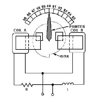
For a given
voltage, the current through coil A is practically constant. However, the
current through coil B varies with the frequency. At a higher frequency the
inductive reactance is greater and the current through coil B is less; the
reverse is true at a lower frequency. The disk turns in the direction
determined by the stronger coil.A perfectly circular disk would tend to turn
continuously. This is not desirable, and so the disk is constructed so that it
will turn only a certain amount clockwise or counterclockwise about the center position,
which is commonly marked 60 hertz on commercial equipment. To prevent the disk
from turning more than the desired amount, the left half of the disk is mounted
so that when motion occurs, the same amount of disk area will always be between
the poles of coil A. Therefore, the force produced by coil A to rotate the disk
is constant for a constant applied voltage. The right half of the disk is
offset, as shown in the figure. When the disk rotates clockwise, an increasing
area will come between the poles of coil B; when it rotates counterclockwise, a
decreasing area will come between the poles of coil B. The greater the area
between the poles, the greater will be the disk current and the force tending
to turn the disk. If the frequency applied to the frequency meter should
decrease, the reactance offered by L would decrease and the field produced by
coil B would increase. The field produced by coil A would remain the same. Thus,
the force produced by coil B would tend to move the disk and the pointer
counterclockwise
Credit:http://bomeelectricity.blogspot.in/
|


No comments:
Post a Comment